WHY do we need differentials?
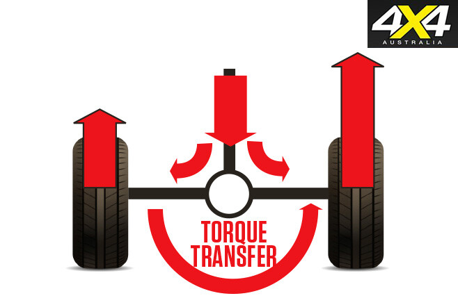
It’s simple: when turning a corner the outside wheel on an axle follows a larger arc than the inside wheel, so the differential gearing allows one wheel to travel at a different speed than the other, while both remain powered. But differential gearing also has the disadvantage of sending the power to the path of least resistance, just like water and electricity.
TORQUE AND POWER
TO properly understand how a diff works you need to understand power and torque, as well as how they relate to one another.
Power is all about movement. The unit for measuring power is the Watt (W).
One Watt is one joule per second. For our purposes, one joule equals 1Nm. Engines power is measured in kW (kiloWatt): 1kW = 1000W.
If you look at the simple equation below you can see there is a relationship between torque, power and rpm: kW= Nm x rpm/ 9549
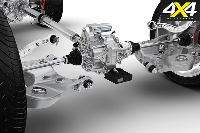
WHAT’S INSIDE A DIFFERENTIAL? THESE days a diff is the term used for the whole drive assembly, including the housing, brakes, axles, etc. But what it actually refers to is the differential gearing assembly inside the heart (carrier) of the diff.
A conventional differential is comprised of four gears. Two are attached directly to the axles, the other two are free to spin on their own axis but are mounted to the carrier, which in turn is rotated by the ring gear.
How do we get the turning power of the driveshaft to the carrier? There are two style of gears normally used:
Hypoid Spiral Bevel Gears THE hypoid gearing arrangement is similar to a spiral bevel gear set-up with the exception of the pinion, which doesn’t share the same axis as the ring gear – in a rear differential application it’s usually mounted lower.
The benefits of meshing the pinion gear on a lower axis is that more gear teeth are in mesh with the ring gear at any one time, meaning power from the engine is distributed on a greater area than bevel gearing. So, for the same size gearing, it’s able to transmit more power and torque. However, the gears slide over each other as they mesh, which creates friction. This friction costs power, so, while stronger, hypoid gearing isn’t as efficient.
There’s one other consideration with hypoid spiral bevel gearing: there are two sides to the gear, a drive side and a coast side, and the coast side is 30-40 per cent weaker than the drive. This is just one of the reasons not to perform a reverse snatch strap recovery.
Spiral Bevel Gears IN a diff application, a small pinion gear is turned by the driveshaft. This then meshes with the ring gear to turn the carrier. Both the pinion gear and the ring gears share the same axis.
HOW DOES IT WORK?
A CONVENTIONAL diff splits the torque equally to left and right (minus some small frictional losses) at all times. It does this regardless of whether both wheels are driving you down the road at 100km/h, or whether one wheel is in the air spinning madly on a low range track.
TRICKY SITUATION CHECK out the traffic going around the roundabout. Notice the front wheels of larger vehicles will be near the outside of the roundabout and the rear wheels will be near the inside. This tells you that when heading around a corner, the front wheels take a larger arc than the rear wheels.
When we lock the centre diff on a full-time 4WD with a conventional diff (or engage 4WD on a part-time 4WD), we remove the ability of the centre differential to compensate for the speed differential between the front and rear when negotiating corners.
This is only an issue on high traction surfaces, like bitumen and slick rock. On loose surfaces such as dirt or gravel the speed differential doesn’t pose an issue, as the surface allows the wheels to slip a little and relieve the tension.
On high traction surfaces the speed differential going through corners will build up a twisting force between the front and rear diffs, leading to an eventual driveline failure.
The first indication of failure is that the car won’t come out of 4WD. Or perhaps you’re driving a part-time 4WD and you can’t push the lever back into 2WD. This is because you’re being prevented from disengaging 4WD by the twisting force in the driveline binding up the mechanism.
To get the car out of 4WD you have two options. First, you can reverse in an arc. This will get the front wheels travelling faster than the rears and will relieve the tension to a point where the centre diff light with stop flashing, or you’re able to push the lever to engage 2WD.
The second option is to head over to the side of the road, put two wheels into the gravel, and continue driving forward. The slippage allowed by the loose surface will dissipate the twisting force, allowing you to get the car back into road mode.
WHY LOCK THE CENTRE DIFF? A LOCKED centre diff will guarantee power is sent to the front and rear diffs.
Another reason to lock the centre diff is to avoid the problems associated with getting stuck in a vehicle with an automatic transmission. If you’re going uphill and get stuck you’ll have to perform a reverse recovery.
If you try this without locking the centre differential, the front wheels will stay locked all the way to the bottom of the hill, due to the weight bias on the rear and the fact all vehicles have a braking bias to the front.
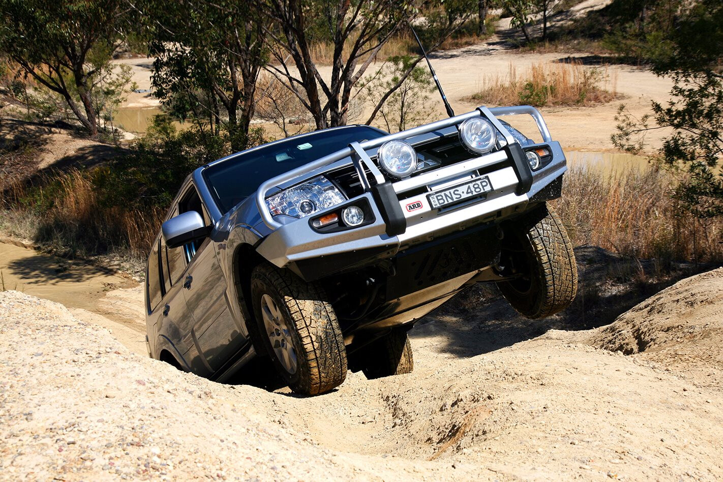
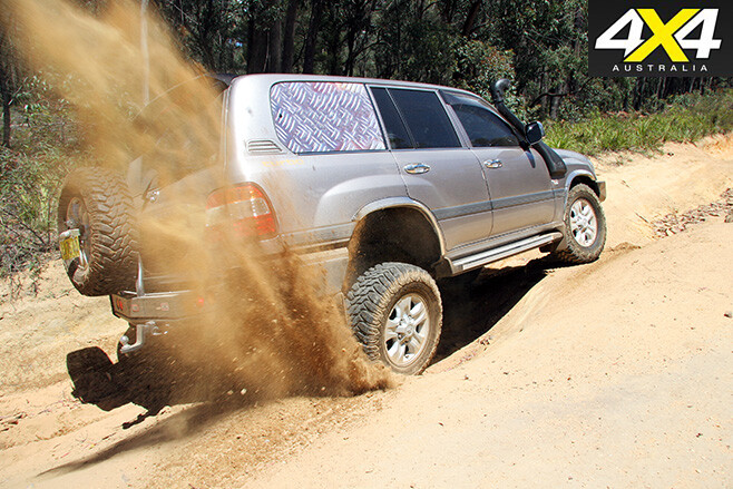
LOCKED DIFFERENTIAL TORQUE DISTRIBUTION WHEN you engage a locker, it effectively removes the differential gearing action from the diff. So now you’ve reverted back to a solid axle between the wheels, and it doesn’t matter if one wheel is on terra firma and the other is 50cm in the air, both wheels will turn at the same rate.
To explain how a locked diff can vary the amount of torque to each wheel, we’ll have to use maths. Let me introduce you to the standard friction equation:
F_r = is the resistive force of friction μ = Friction co-efficient for the tyre against the terrain you’re travelling across. N = Normal force (in Newton-metres), which is the weight of the car pushing the tyre down on the terrain. Let’s look at a scenario where one tyre is on mud and the other is on a road surface. Both of the tyres are exerting a force of 1000N.
Road μ = 1 Mud μ = 0.3 Mud F_r=μN F_r=0.3 x 1000 F_r=300 Road F_r=μN F_r=1 x 1000 F_r=1000
Adding both together you get a total resistive force of friction 1300N, which means 77 per cent of the torque is delivered by the road-side tyre and 23 per cent by the mud-side tyre.
CONVENTIONAL DIFFERENTIAL TORQUE DISTRIBUTION LET’S now look at the same scenario, but this time we’ll leave the locker alone. Remember the small gears that are free to rotate within the carrier and are connected to each axle? Well, they ensure the torque is distributed evenly between both axles and there’s no torque bias to either side.
You still have a potential of 300N of resistive force of friction with the side in the mud, but the side on the road will also only get 300N thanks to the small, freely-rotating gears in the middle of the diff. So that’s a total of 600N. But the good news doesn’t end there.
Have you noticed when you’re pushing a large heavy object like a couch it’s hard to get going, but once it’s moving it seems like it’s not as hard to push? Well, that’s actually a measurable phenomenon known as sliding or kinetic coefficient of friction, and it will be measurably less than the static coefficient of friction.
So now as you put the foot down and start spinning the wheel in the mud, the coefficient of friction will drop from a μ of 0.3 to 0.2. Don’t forget with an open differential the torque on one side is equal to the other, so now instead of 600N we’re down to 400N. In the same scenario we’ve gone from 1300N with a locked differential to 400N with the standard open differential.
LIMITED SLIP DIFFERENTIALS
The purpose, as the name suggests, is to limit the amount of wheel slip. However, there are several different variations with different degrees of effectiveness.
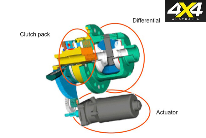
CLUTCH-TYPE LSD This type has a multi-plate clutch pack similar to that in a motorcycle. One side of the clutch assembly is connected to the driveshafts and the other to the differential gear carrier. Various methods such as ramps or the natural force of separation between gear teeth are used to engage the clutch pack when the differential experiences one wheel turning faster than the other, which then transfers some of the power to the slower-turning wheel.
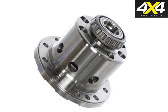
ONE-WAY, ONE AND A HALF, AND TOW-WAY A one-way LSD will only provide the limited-slip action in one direction – for example, under acceleration but not under braking. By contrast, a 1.5-way LSD will provide differing amounts of slip limitation under acceleration and braking, which can aid stability under heavy braking. A two-way LSD will provide the same amount of limited-slip effect under both acceleration and braking.
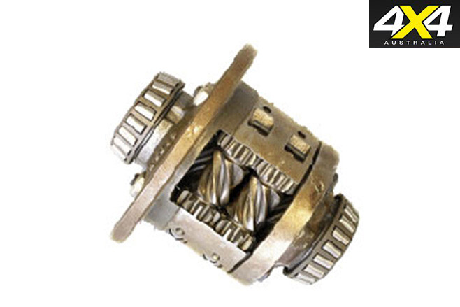
TORSEN The torque-sensing differential is a limited slip-type differential that uses the one-way action of worm drive gearing to limit slip. They also have the ability of being manufactured with a TBR (torque bias ratio), where there is an ability to send more torque to the rear wheel in a centre differential application.
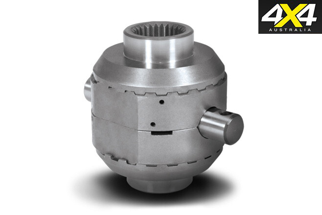
AUTO LOCKER When thinking of auto lockers, many think of ‘lunchbox lockers’ that replace the spider gear mechanism in the middle of differential carrier. Probably better referred to as un-lockers, lunchbox lockers are locked when driving under power in a straight line. When they experience different torque loads, such as coasting around a corner, they unlock. This can make for interesting handling characteristics on the road, and if installed in the front they’re much better in combination with a part-time 4WD system.
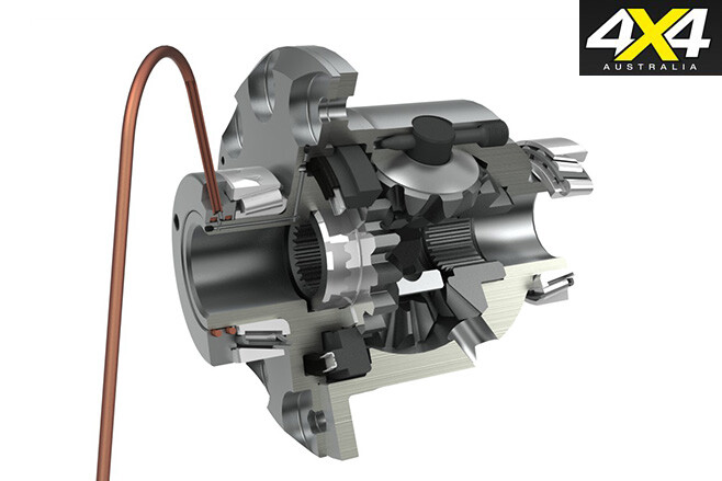
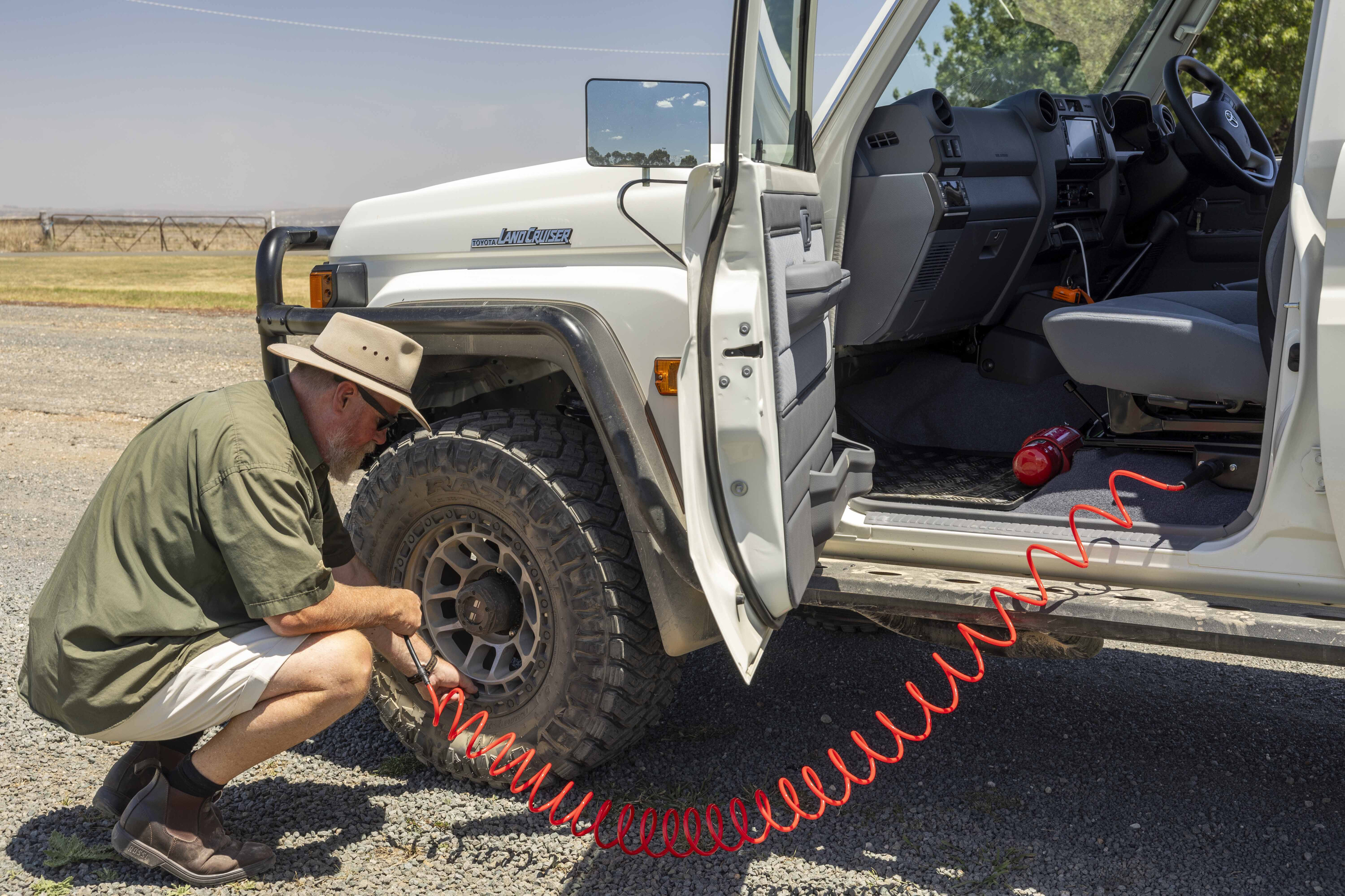
SELECTABLE LOCKER Viewed as the Holy Grail by many, selectable lockers come in two main flavours: air operated (TJM/ARB) and electromagnetic (ELocker). Both pneumatic lockers use a simple dog clutch-type mechanism that removes the differential action when activated. However, the ELocker uses a pin and ramp mechanism to operate a series of pins that lock the differential. When transitioning from forward to reverse, they unlock then relock due to the forward and reverse activation ramps used.
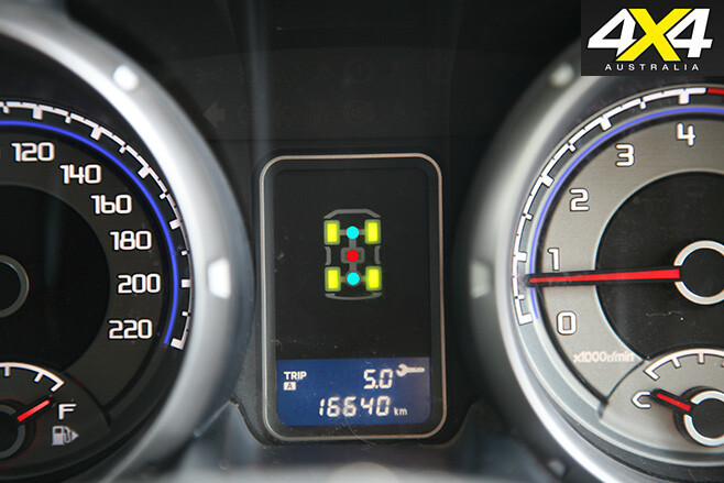
TRACTION CONTROL There are two main types of traction control: one reduces engine power, the other reduces the differential’s ‘power to the path of least resistance’ characteristic. Modern systems monitor individual wheel speeds and if two wheels on the same axle are travelling at differing speed it brakes the spinning wheel – this requires more torque from the engine. As there is always even torque on either side of a conventional diff, the slower wheel receives extra torque. Early systems weren’t great but now traction control is almost a viable alternative to lockers – the latest LandCruisers and Pajeros are particularly good.
LOCKERS VS TRACTION CONTROL? IF YOU’RE heading down a steep, undulating hill, a double-locked car can’t be beaten, as it reduces the weight placed on alternating wheels. An unlocked car will lock the brakes and intermittently slide, before grabbing traction as the weight comes back on the wheel. A locked car won’t lock wheels and then slide down the hill, as both wheels are mechanically locked together, acting as a solid unit.
If going uphill, lockers again reign supreme. Traction control waits for the axle to start losing traction before it counteracts by braking the spinning wheel. This takes time, so you’ll always lose momentum waiting for traction control to react – and that might be enough to stop you in your tracks.
However, anyone who has driven a double-locked car will tell you that cornering isn’t its strongest point. On the flipside, traction control is smart enough to operate even around a hairpin bend.
TORQUE VECTORING DIFFERENTIALS A CONVENTIONAL diff gearing system is located in the centre, but on either side of the carrier is a clutch pack that (when electronically engaged) is able to mechanically link the axle directly to the carrier. Using electronic manipulation of the clutch packs, the designers are able to vary the torque to each wheel. When turning around a bend, the computer is able to provide more torque to the outside wheels, therefore improving turn-in and handling characteristics.
If used as the centre diff in a full-time 4WD application, you could have a vehicle with a bias toward the rear wheels for everyday driving, but could split the torque 50:50 when off road. This differs from a Torsen diff, where the torque split is mechanically set and can’t be altered on the fly.
